Connecting Hardware
This section of the user guide explains how to connect hardware such as batteries, motors, servos and sensors to the YRK to make a complete electronics hardware design for a robot. The simplified
pin-out diagram is shown below, a more detailed view is available in the Documents sections.
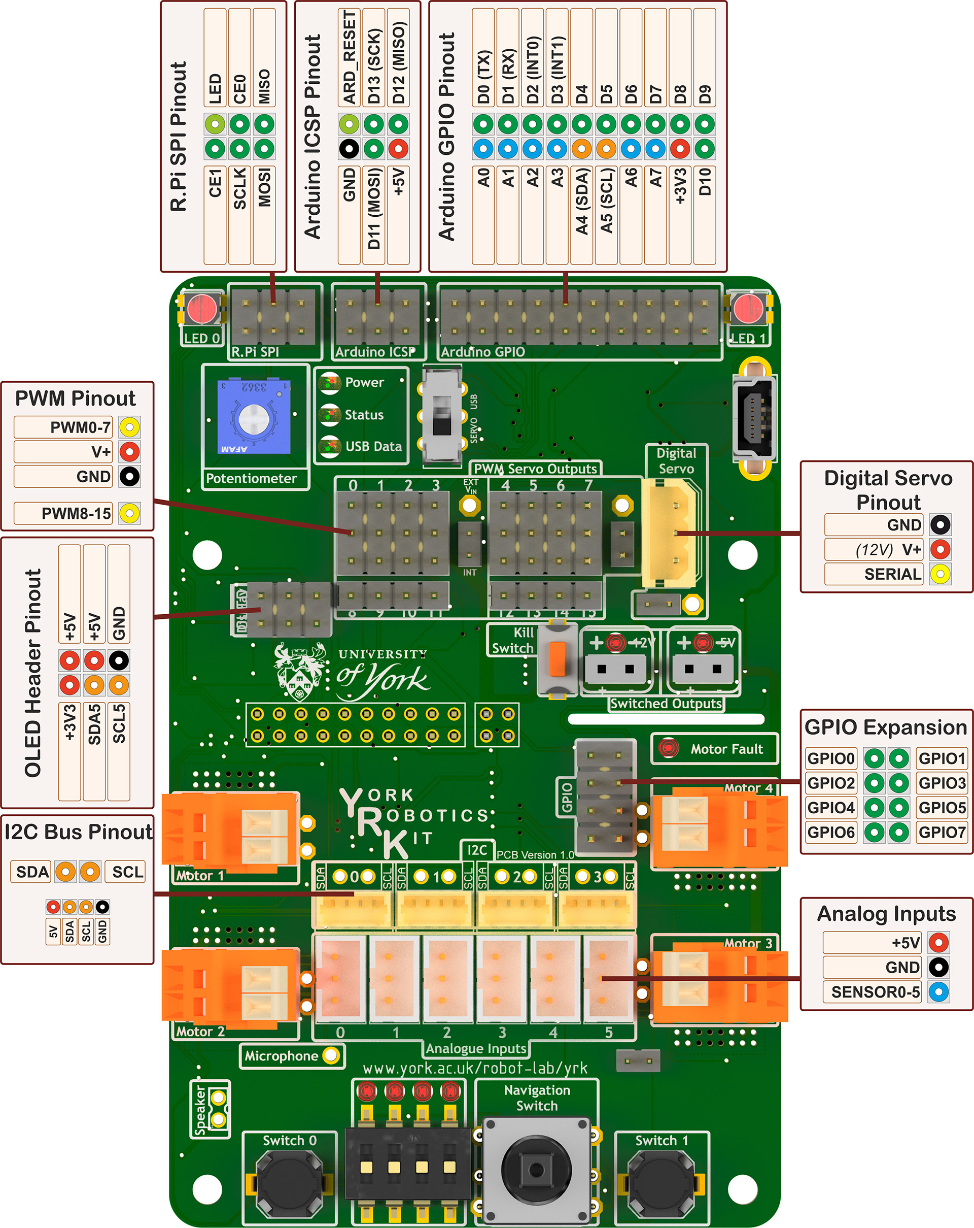
Pin-out and wiring diagram for York Robotics Kit
Power Supply
The YRK can be powered by any standard 12V power supply with a 2.1mm DC jack (centre positive) and 3A or greater current rating. Using a tethered power supply such as this is strongly recommended to be used as much as possible to preserve battery life if motion of the robot is not required. Do not connect a power supply when the battery is connected and vice-versa (shutdown between changing power sources by pressing the power button).
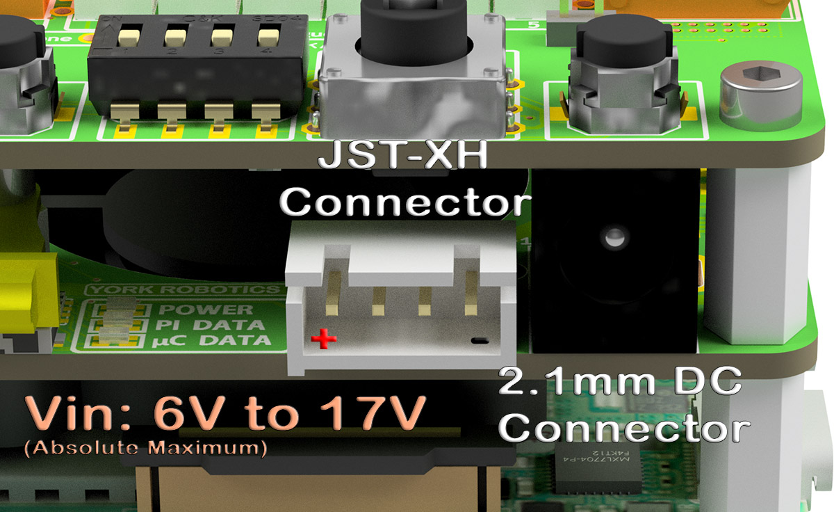
Location of the 2.1mm DC jack and JST-XH battery connector
Battery
The YRK is primarily inteded to be run using a 3-cell Lithium-Polymer battery pack, connected using the industry-standard JST-XH 4-pin 0.1” pitch connector used as the balance charging connector. These connectors and cables are typically rated for 2A current which is enough for normal use of the YRK [which has a 2.5A input Polyfuse]. Where high currents are needed, such as powering multi servo motors, the high current cable from the battery should be soldered (via a self-made adapter) to the appropriate power points on the YRL040 PCB.
The YRL039 power supply board has a low-voltage dropout and should work effectively from voltages as low as 5.5V to a 17V high, enabling 2-cell and 4-cell operation Li-Po (and a range
of other lead-acid, Ni-Mh, NiCad, LiFe and other rechargeable battery technologies, provided they can provide around 5A peak current at 5V). Relevant changes to the yrk.settings file should
be made to reflect the battery used if not the default 3-cell configuration.
Only the outer-two connections of the JST-XH connector are used. It is also possible to use the 2.1mm DC jack as the input source. Always disconnect the battery after use and charge using a
suitable charger (in a fire-safe bag if using a Li-Po battery pack). The power supply board is not presently optimised for ultra low-current and the residual current draw (from the ATMega microcontroller)
will discharge the battery even when beyond a damagingly low value. General convention suggest a per-cell voltage of 3.0V is the absolute minimum a Li-Po battery should be allowed to discharge to (ie 9V
for 11.1V 3-cell battery) before permanent damage is likely to be done. The Arduino code on the YRL039 can be configured to automatically switch off power supplies below a critical low voltage but this
needs to be correctly configured for the battery technology used. If the core.py software is not run the user must implement some method of periodically monitoring the battery voltage and provide
suitable user warnings when low levels are reached, otherwise batteries can rapidly deteriorate.
The YRK connected to a Raspberry Pi 4 will typically consume approximately 800mA on the 5V rails at idle, most the current powering the Raspberry Pi and a smaller amount of the 5V_AUX rail (mostly powering the fan and LEDs). Motors and sensors will add significantly to this load. This relatively high idle load means that battery capacity should be at least 1000mAH, and this capacity would provide at best around 1 hours use (and significantly less in high load cases). The use of a lower-power Raspberry Pi, such as the model 3A, might be considered when long battery life on small batteries is desired, at the expense of memory, processing capability and expandability.
DC Motors
There are four serial H-Bridge motor drivers, based on the DRV8830 TI Motor Driver. The PCB design limits each motor driver to approximately 800mA current, powered from the 5V_AUX supply. Having all four motors drawing this peak current for sustained periods will exceed the rating of the power supply. This current limit (and voltage rating) does restrict the motor driver to using small motors, such as the widely-available 3mm shafted micro-metal gear motors. Before using a different size of motor it is recommend to check (such as by using a bench PSU) what the stall and no-load currents at 5V.
The holes on the unpopulated PCB allow the motors to be connected to either Wago push-fit terminals or (on PCB version 1.1) 3.5mm pitch screw terminals.
With either connector, a remaining pair of holes will be accessible on the PCB should a direct soldered lead be required. The motor driver can detect fault
conditions (undervoltage, overvoltage and overtemperature events) and when the yrk.core program is running these will be indicated by the red fault LED above
the top-right motor output. If persistent fault conditions check the motor is working correctly and doesn’t draw excessive current for the design; micro-metal-gear
motors are relatively delicate.
Servos
The YRK can control both standard analogue servo motors (8 directly attachable, 8 further channels available via breakout), and digital servo motors via an Arduino-based software interface.
Analogue Servos
Analogue servos are operated using a PCA9685 I2C LED driver IC. Whilst primarily designed to allow I2C brightness control of up to 16 LEDs, it can effectively work as a analogue servo controller. Analogue servos typically operate with a 20mS period width (50Hz PWM frequency), and expect a pulse width in the 1ms - 2ms range [with 1.5ms being the middle point of the servo rotation]. The PCA9685 lets us fix the PWM frequency for all outputs and effectively becomes an I2C servo controller.
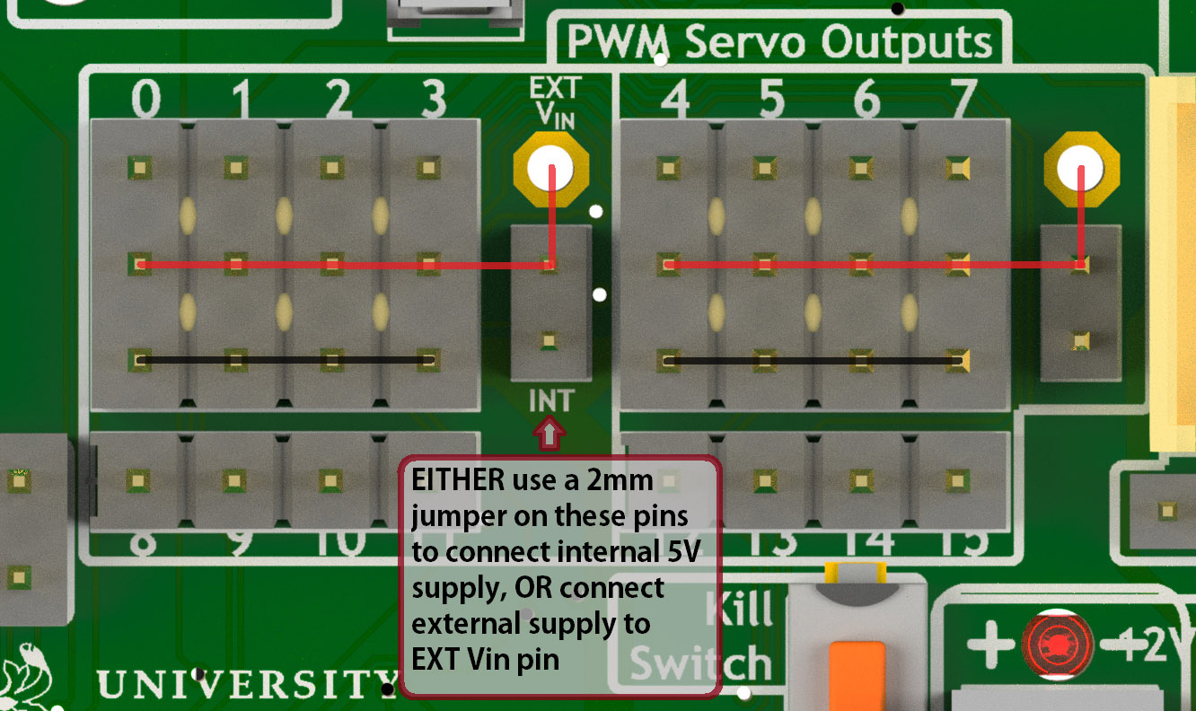
Power connections for the 2-banks of PWM analogue servo outputs
There are 16 available outputs on the YRL040 PCB, located in the middle-top of the PCB. Eight of these are available as full 3-pin outputs, where DC power (+ and GND) can be supplied to the servo. Most analogue servos come hardwired with a three-pin 0.1” pitch socket attached at the wire tail. Different colour schemes are used for the wiring, and it is important to be careful checking the orientation of the plug; as a general rule the lightest colour will the control signal (top side of connector) and the darkest will be ground.
Pin Number |
Signal |
Futaba |
JR |
Hitec |
|---|---|---|---|---|
3 [Top] |
Control |
White |
Orange |
Yellow or White |
2 |
V+ |
Red |
Red |
Red or Brown |
1 [Bottom] |
Ground |
Black |
Brown |
Black |
These 8 complete connections are split into two banks of four. Each of these banks can be supplied with DC either by the internal 5V supply (by using a 2mm jumper), or to an external positive input, by soldering a suitable cable onto the hole on the board. If the internal supply is used, the total current for each bank must not excede 1A (a pair of 0603 fuses are included on the board . This is due to the overall current limitations on the board. For this reason it is strongly recommended to only use very small, low-current servos, and to spread load across both banks, if using the internal supply.
Another 8 PWM outputs are available just below the primary 8, but these cannot be used directly with a 3-pin connector. In situations where a large number of servos are required simultaneously, a small break-out board allowing direct power connection would be a sensible option. The circuit is the same as used on the Adafruit 16-channel PWM servo driver.
Code for the analogue servo control is in the yrk.pwm module. Examples of the use of the PWM
driver to control servos can be found in examples.console.
Digital Servos
The York Robotics Kit is designed to support digital servos from the (Dynamix AX- and MX- series) via code on the Arduino microcontroller.
To do: This section and code not completed yet!
Analogue Inputs
The YRK includes an I2C based, 8-channel, 8-bit analogue to digital converter IC. Whilst this can be used for anything requiring analogue inputs, it is primarily intended for use with analogue distance sensors manufactured by Sharp, in particular the 2Y0A21 and 2Y0A41 models. The reference voltage is set to 2.5V, meaning the returned value is approximately equal to the voltage mulitplied by 100.
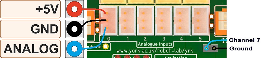
Analogue input channels 0-5 (JST PH sockets) and channel 7
Cables
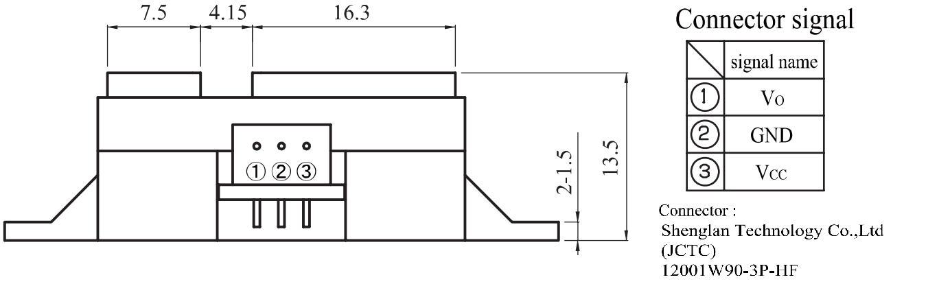
Wiring diagram of Sharp Distance Sensors
The Sharp distance sensors use a 3-pin JST PH series connection (note the newest models use a JCTC connector instead of a JST). 6 matching JST-PH connections are available on the York Robotics Kit, each providing the analogue-input and 5V power supply required by the sensor. A suitable complete pre-made harness has not been sourced, but it is possible to buy pre-crimped leads from JST which make creating harnesses quick and simple (if expensive).
JST Part Number |
Farnell Part |
Description |
Unit Price [per 100] |
|---|---|---|---|
01SPHSPH-26L150 |
2065431 |
150mm PH-PH Lead |
0.416 |
01SPHSPH-26L300 |
2065432 |
300mm PH-PH Lead |
0.439 |
PHR-3 |
3616198 |
3-pin PH Receptacle |
0.032 |
To assemble the harness, place one receptacle face-up and the other face-down then connect top-to-top, middle-to-middle and bottom-to-bottom, as seen in the photograph below.
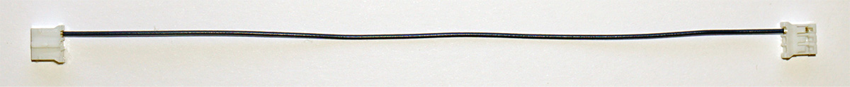
Assembly of first wire in JST PH cable for use with Sharp Distance Sensors
Potentiometer
Channel 6 of the ADC is connected to a potentiometer (variable resistor) at the top-left of the PCB. As the pot’ is rotated clock-wise from left to right the ADC output value will decrease from 255 to 0.
Other ADC Inputs
Channel 7 of the ADC is routed to the left pin of a 2mm pitch pin-header below the channel 5 connector. Any of channel 0-5 and 7 can be used as a general purpose ADC input (8-bit, with a 2.5V reference voltage) by using the raw reading value. There is also the potential to use any of the 8 available analogue inputs on the ATMega microcontroller which offers 10-bit resolution (see section on Arduino below).
I2C Devices
The I2C interface is widely used for many robotics sensors and accessories. The YRK uses a PCA9548 I2C switch, which splits the master I2C bus into 8 individual busses, allowing the use of repeated I2C addresses across multiple ports. This allows, for example, the use of multiple I2C distance sensors which share the same I2C address, by connecting them to different busses. Most I2C devices (capable of operating in 400KHz fast mode) can be attached provided they do not use the address 0x70 which is used by the switch.
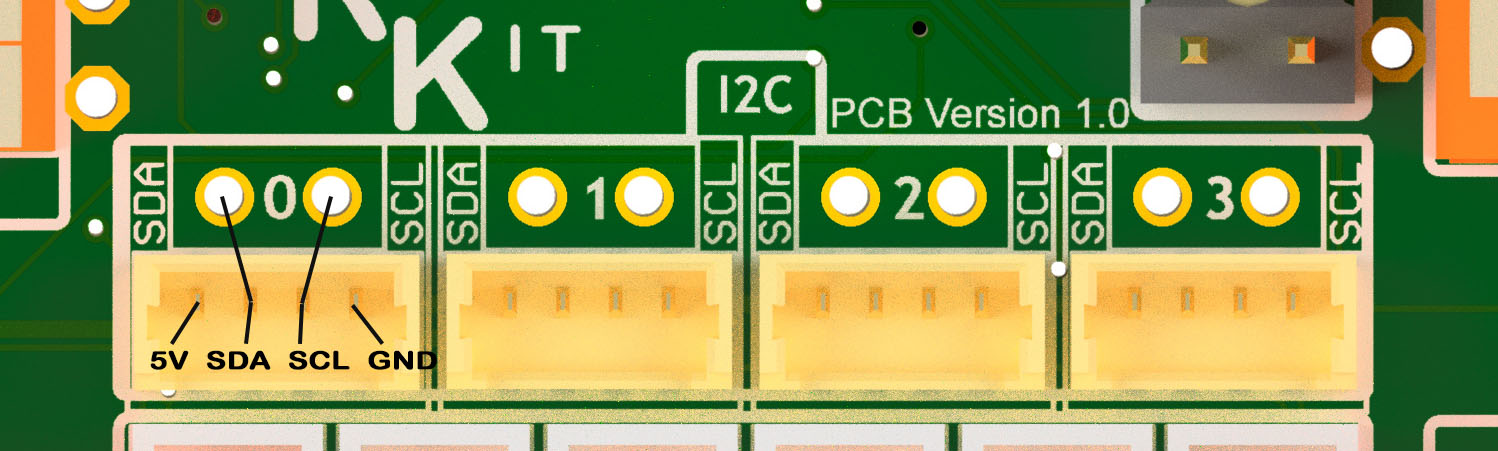
Closeup of I2C (channel 0 - 3) Picoblade and 0.1” connectors
The I2C switch has a kernel-level driver, meaning that the individual switched busses appear to the user as
different I2C root devices (each has its own file handle at /dev/`i2c-XX). The actual address of the bus
is different when used on the Raspberry Pi 4 hardware and earlier versions, as the Raspberry Pi 4 hardware
can support more native I2C busses (not used in the YRK). On the Raspberry Pi 4, the switched busses map
to file descriptors /dev/i2c-6 to /dev/i2c-13 from channel 0 to 7, and to descriptors /dev/i2c-3 to /dev/i2c-10
on earlier version of the Pi.
The first four channels are unused and are intended for user additions. These SDA and SCL signals for these channels are each routed to unpopulated 0.1” pitch holes on the YRK PCB, and also to 4-pin Molex Picoblade headers. The Picoblade headers (1.25mm pitch) include a 5V and GND signal. These are directly compatible with sensor boards developed at York such as the YRL013 multi-sensor board and the YRL019 thermal-imaging sensor board. Note that all i2c channels except channel 4 are pulled-up to 3.3V; channel 4 is utilised by the PWM driver and the Arduino (see below) and is pulled-up to 5V.
Arduino
The YRK includes a ATMega328P microcontroller, running at 5V and connected to both an
FTDI serial to USB interface and to the I2C switch (on switch port 5, which is /dev/i2c_11 on Pi 4).
The microcontroller is effectively a clone of an Arduino Nano board (albeit with a different pin layout).
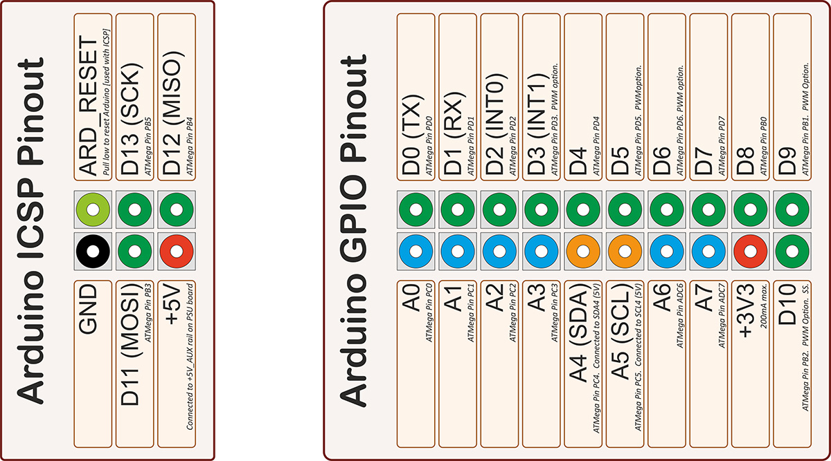
Pin-out for the ATMega microcontroller (Arduino nano clone)
Programming Bootloader
Before normal use, the ATMega328P must have bootloader code uploaded to it which allows it to be programmed
using the serial to USB interface. This can be done using various AVR programmers, but can also be done
using a separate Arduino board and the Arduino as ISP
program. The best settings in the Arduino IDE are to use Board: Arduino Pro or Pro Mini and Processor: ATMega328P (5V, 16MHz).
Uploading Code
Once the bootloader has been uploaded, the Arduino can be programmed via the mini-USB port at the top-left of the board. Note that the 5V power on the mini-USB is not connected to the YRK (this means the YRK board needs to be powered on if programming over USB). It is possible to program the Arduino from the Raspberry Pi, if a USB cable is connected from the mini-USB to the USBs on the Pi. This can be done either using Arduino IDE, or from the command line *(avoiding the need for X-windows). The command line upload would look similar to this statement:
arduino --upload --port /dev/ttyUSB0 --board arduino:avr:pro:cpu=16MHzatmega328 --verbose-upload my_code.ino
It is important to note that to use the mini-USB interface the slide-switch must be in its upper position. The switch directs the TX and RX serial output pins from the ATMega microcontroller to either the FTDI serial to USB interface (and mini-USB port), if it is in its upper position, and combines the lines via a tri-state buffer for use with the digital servo port in its lower position.
Switched Outputs
The board contains a pair of FET driven switched outputs which can be used when it is necessary to turn on simple switched loads. Typical uses might be powering buzzers and sirens, LED light fittings and lamps, beacons, solenoids and relays. One output is connected to the 5V_AUX supply, the other is marked as 12V and is connected to the battery or DC input. Both switched outputs are protected by a 1A 0603 quick-blow fuse. The outputs are connected to 0.1” sockets (preferred over header as harder to short-circuit).
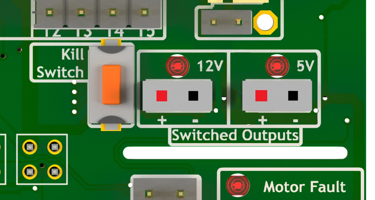
Close-up view of 12V and 5V switched output connectors.
It is important to note that the switched outputs use low-side switching, meaning that the + output is connected directly to the (5V or battery) supply rail but the - is not connected to ground; never use the switched outputs on loads that require the grounds to be coupled together. It is recommended to limit the current on the switched outputs to below 500mA if possible. If a higher current (or circuit with coupled ground) is needed, consider using the switched load to drive a relay or solid-state equivalent. Note that the actual potential difference will be a little lower than the indicated amount due to the voltage drop across the FET. Consider using a flyback diode across inductive loads (such as relays and solenoids).
Raspberry Pi Interfaces
One consequence of the number of hardware features on the board is that very few Raspberry Pi GPIO pins are available for use. The 5 pins that are available (pins 19, 21, 23, 24 and 26) are the pins that can be used as the SPI0 interface on the Raspberry Pi, allowing SPI peripherals and expansion to be added to the YRK. These pins can also be used a general purpose IO pins if the SPI interface is not required.
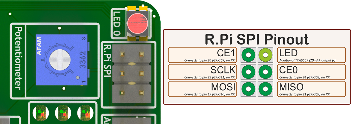
Close-up view of Raspberry Pi SPI interface at top-left of board (rotated 90 degrees)
Additional GPIO
A bank of 8 user-GPIO pins connected to the bank 0 of the (U13) PCA9555PW GPIO expansion IC is available for use. The API for the pins is not yet written.
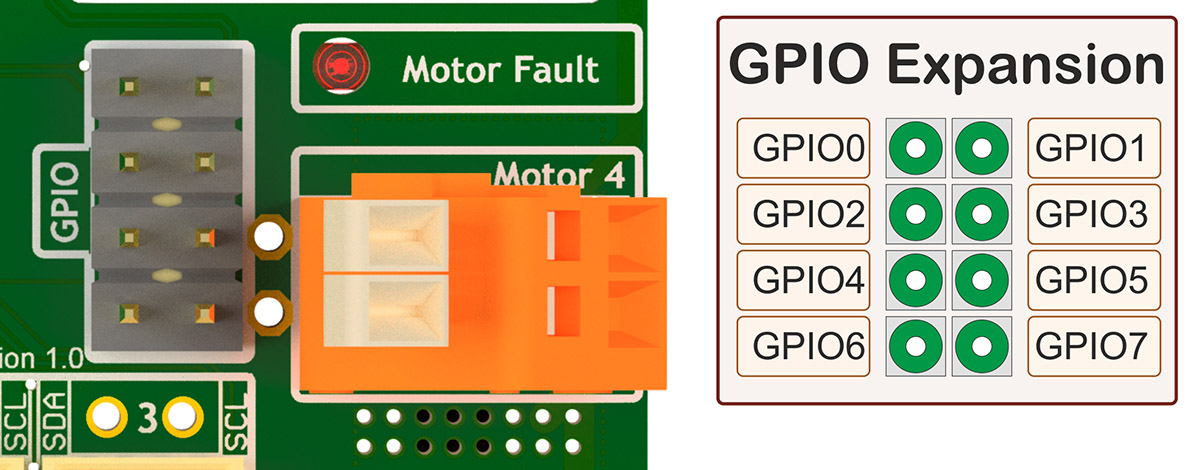
Close-up view of 8 user GPIO expansion pins
There are several other expansion pins on the board that can be used as general purpose digital IO pins, for connecting extra hardware
such as switches, LEDs, transistor switches and others. The TCA6507 LED driver that drives the RGB LEDs has one additional output that
is configured to give a 20mA drive current to an external LED (or multiple LEDs in series or parallel). The cathode pin of the LED(s) should
be attached to the LED pin of the R.Pi SPI header at the top-left of the PCB; the anode can be connected to either a 3.3V or 5V pin as needed
(blue and white LEDs may require 5V due to their greater forward voltage). The PWM (analogue servo) outputs can also be used to drive LEDs
or other outputs if appropriate (the PCA9685 driver is actually marketed as a LED driver).
Display
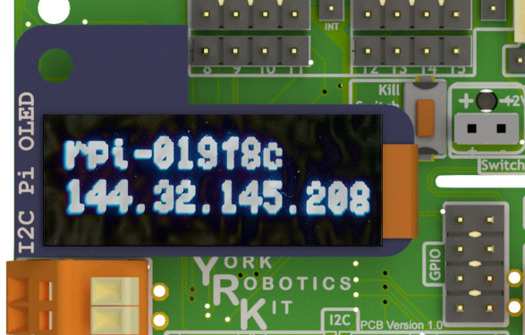
Close-up view of Adafruit I2C OLED display module on YRK
The board has been designed such that an Adafruit PiOLED 128x32 pixel display module can be directly connected to the main board. The software library written by Adafruit has been adapted so that it performs more reliably on the switched I2C bus (note that I2C is a relatively slow bus and even small displays take quite a lot of data to drive, so infrequent updates are recommended).
Obviously it may be desirable to relocate the display elsewhere on a robot chassis if the YRK and Pi are enclosed within; this simply requires the use of either 4 jumper leads or ideally a 3x2x0.1” IDC patch cable from the header on the YRK to the receptacle on the display PCB.
It should be possible to use different I2C (and also SPI) displays but some alteration of code may be necessary to handle the i2c switch. It will not be possible to use any display modules which rely on a large number of GPIO pins on the Raspberry Pi as these are not available once the YRK is added. If a larger display is required, consider using the official Raspberry Pi touch display (7” diagonal) or a HDMI based solution.
Loudspeaker
The YRK includes a monoaural amplifier attached to one of the PWM outputs of the Raspberry Pi (GPIO12). When correctly configured, the Raspberry Pi (using the ALSA audio system) can be set to play audio using its internal PWM. The YRL040 PCB includes a Texas Instruments TPA2005 class-D audio amplifier IC, which is capable of producing up to 1.4W when using an 8-ohm speaker. It may be possible to use lower impedance speakers (down to 4-ohm) but note the amplifier is using the 5V_AUX and would be operating out-of-specification at 4-ohms. Audio generated from PWM outputs is generally very noisy and low in fidelity but is adequate to generate simple sounds and speech synthesis.
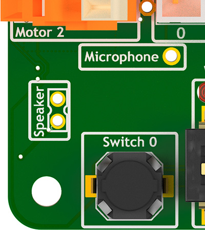
Location of the speaker connection at bottom left of YRL040 PCB
The speaker output is routed to two pin holes near the bottom-left corner of the YRL040 PCB (being mono the phase of the speaker doesn’t matter). A 2-pin, 2mm pitch header can be soldered in place here to make attaching a removable speaker easier; it hasn’t been done by default as the case has space for a 17mm x 11mm speaker to be connected which would be hard-wired to the underside of the YRL040 PCB.