Introduction
The York Robotics Kit is a platform design to allow the Raspberry Pi family of microcomputers to control a wide variety of robotics hardware with the minimum extra electronics assembly. It comprises a pair of PCBs which attach above a Raspberry Pi SBC (single-board computer). This document describes the initial version of the York Robotics Kit, comprising the YRL039 Power Supply Board and the YRL040 YRK Board, which are primarily designed to be used with the Raspberry Pi 4 B and Raspberry Pi 3 B(+) series of computers.
This is still very much a prototype and development design and should be regarded as such!
Construction
This document assumes PCBs have been manufactured and all components assembled (see separate documentation for PCB construction). The PCBs have been designed using Autodesk Eagle software and are both 2-layer construction, designed to conform to Eurocircuits Class 6 design guidelines. Information about the Eagle CAD source files, schematic diagrams and layout documents can be found in the Schematic Diagrams section. Both PCBs are two-layer boards and designed to be both relatively cheap to manufacture and relatively easy to assemble.
PCB Name |
Description |
|---|---|
YRL039 |
Power Supply PCB |
YRL040 |
Main YRK PCB |
YRL039 Power Supply
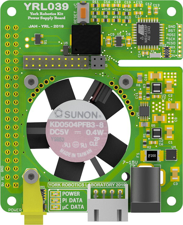
YRL039 Power Supply
The YRL039 Power Supply Board as designed to serve six main functions:
Take a battery or DC input and convert into stable, separate 5V supplies. Each of the 2 5V supplies is rated to provide at least 2.5A current. One supplies the Raspberry Pi (including USB peripherals), the other provides the 5V_AUX rail for most other components.
Provide an interface between Pi GPIO pins and respective pins on YRL040 PCB. It was desired to rotate and reduce in size the 40-pin GPIO header on the Pi to allow more space for edge-mount connectors on either side of the YRL040 PCB (for motors, sensors and servos etc).
Provide hardware monitoring of temperature, input voltage, output voltages and output currents.
Provide a software on-off power button with forced shutdown option
Provide an 35mm fan based active cooling for the Pi microcontroller, the power supplies and the YRL040 mounted above.
Generate simple audio tones using a Piezo buzzer
All the components except for the fan are mounted to the top-side of the PCB. The TPS82130 TI 3A Step-Down Converter Module is core components of each of the two 5V power supplies.
Programming the YRL039
The YRL039 uses at ATMega328P microcontroller to control the soft-power switch, make audio tones and report voltage, current and temperature readings using the I2C
bus. The standard code is found in the atmega_code/yrl039_arduino subfolder of the GIT repository; if special functionality is required, such as lowering the
battery-low cutoff voltage or reducing the temperature at which the fan operates, it may be necessary to reprogram the microcontroller. This is easiest to do with
the YRL030 FTDI Interface and Programming Board that contains the 8-pin, 1.25mm pitch connector used for programming and serial data; the YRL030 can be used
for both flashing the bootloader to the microcontroller using the ICSP interface and also uploading code and debugging data using a USB serial interface.
YRL040 Main PCB
The main YRL040 PCB has been designed such that the vast majority of electronic components are surface mounted on the underside of the board.
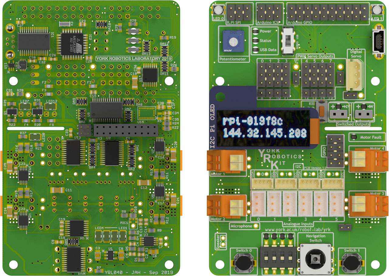
YRL040 Main PCB (Bottom and Top Views)
The board contains the following interfaces:
8-way I2C switch providing 4 user busses at 3.3V, a 5V bus used by on board PWM driver and Arduino, a bus design for use with an OLED display module, a bus for communication with the YRL039 PSU and a bus for all other internal connections.
4 I2C H-Bridge Motor Drivers based on the TI DRV8830 IC.
16-channel PWM Driver suitable for use with analogue servo motors
16-channel GPIO expander providing 5-way navigation switch, 4-way DIP switch, 2 push-button switches and LEDs
Addition 16-channel GPIO expander providing motor driver fault monitoring, a 5V and a 12V switched output, a kill-switch and 8 user GPIO pins
8-channel, 8-bit ADC with 6 ports optimised for use with Sharp analogue distance sensors, a channel connected to a potentiometer and a spare channel.
A mono audio amplifier connected to a PWM audio channel on the Raspberry Pi
An I2S mono microphone module
An Arduino compatible ATMega328P microcontroller for use with wheel encoding, digital servo motors and other tasks.
Assembly
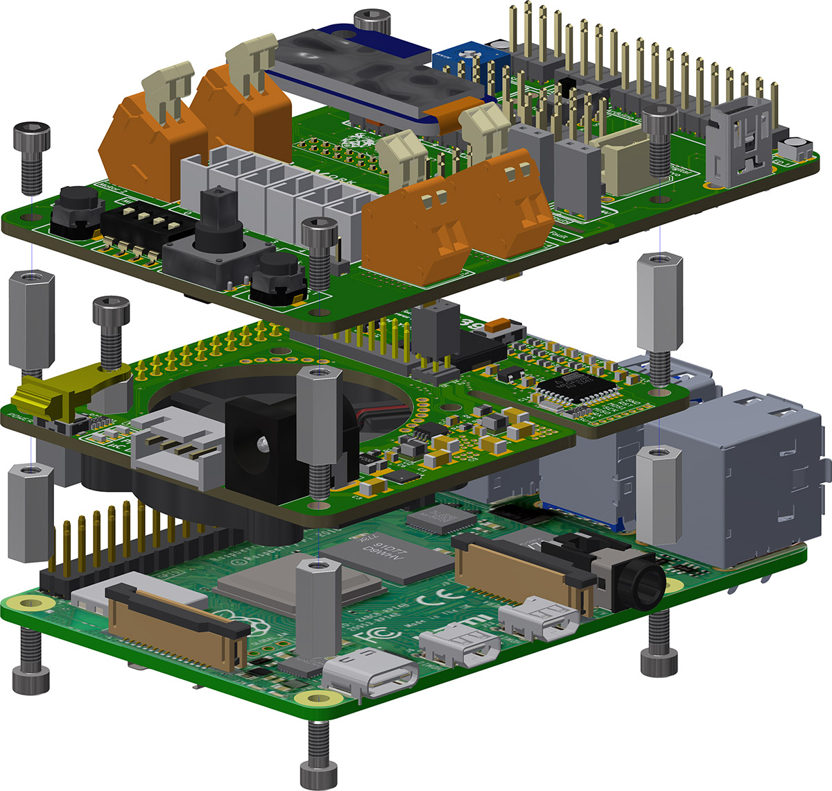
Exploded view of YRK showing 11mm standoffs and M2.5 screws
The YRL039 attaches above the Raspberry Pi PCB using the 4 x 11mm length, M2.5 diameter standoffs. Another layer of 4 x 11mm standoffs is used to attach the YRL040 PCB above the YRL039 power supply PCB. It is recommended that M:F (male one end, female other) standoffs are used in the upper layer, with the male threads pointing downwards through the YRL040 PCB, then M:M standoffs (sometimes called spacers) below on the bottom layer.
The assembly can be mounted inside a further case, described below, or can be mounted directly onto a chassis or further standoffs. Consideration of the airflow path should be taken, particularly when fully enclosed inside a robot. The Raspberry Pi alone can generate a significant amount of heat and rapidly reaches a point at which it will throttle clock speed if it is not adequately cooled.
Case
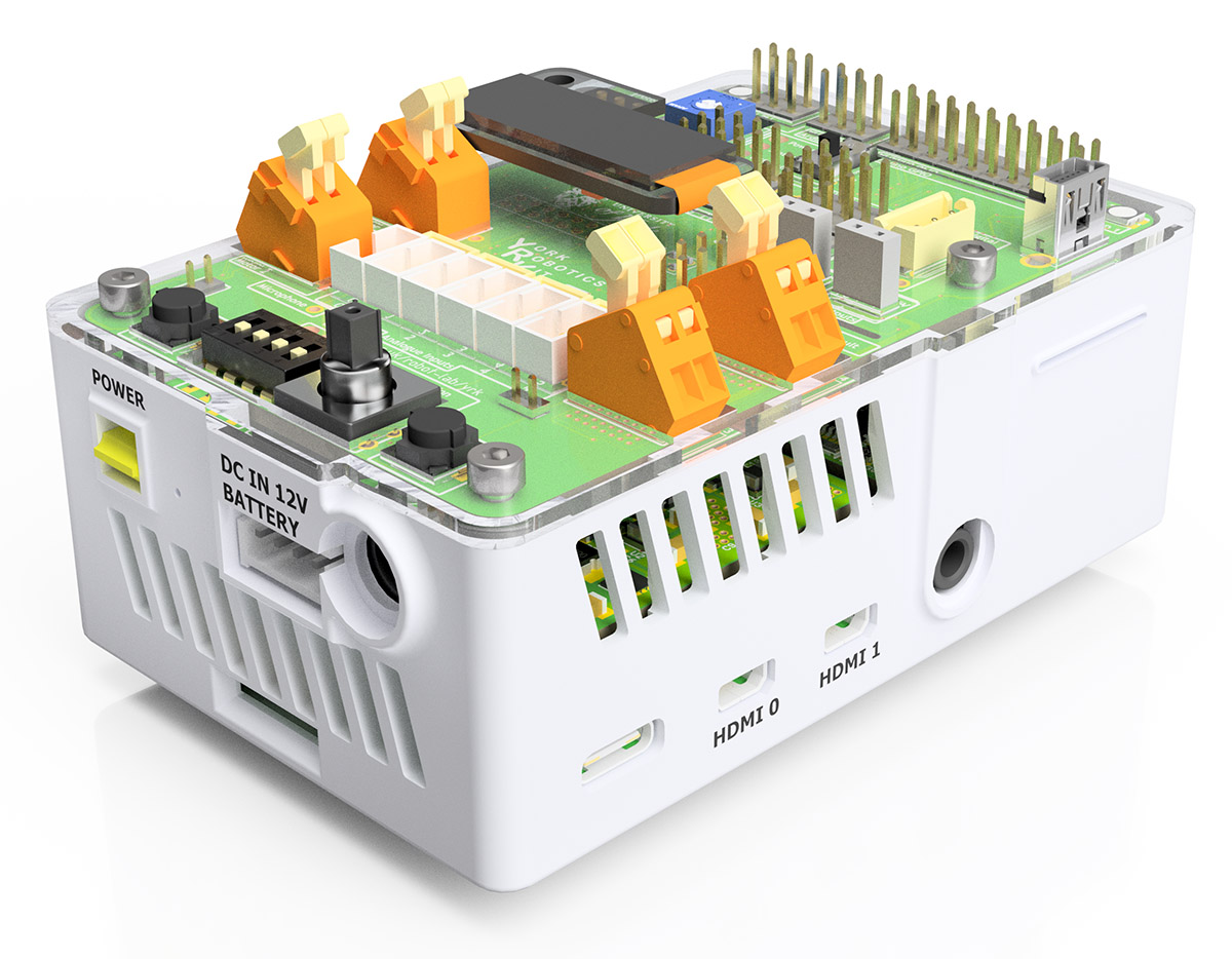
York Robotics Kit mounted in Polyjet case
A case designed specifically for the Raspberry Pi 4B series of computer, the YRL039 and the YRL040 PCBs has been designed. This particular design is intended to be printed on a Polyjet class of 3D printer, with very fine tolerancs and gaps. A more general design for FDM could easily be implemented, but is not essential. If designed a new housing [or placing assembly within a robot chassis design etc], consider airflow route carefully. Pi 4 devices will generate substantial heat and the fan needs some route to direct air across the Pi 4 CPU, but also ideally the power supply elements on the top side of YRL039 and also components on the underside of the YRL040 PCB. Those components likely to dissipate the most heat [motor drivers, PWM driver, amplifier and active outputs] are all towards the lower half of the PCB, which should receive forced convection from the fan.